Research Article
Volume 1 Issue 4 - 2017
Comparison of the Dimensional Stability of Splinting Material with Different Polymerization Times
1Jason P. Kiangsoontra, DDS, MS – Private Practice, Vienna, Virginia, USA
2Heather J. Conrad, DMD, MS – Associate Professor and Director, Department of Restorative Sciences, University of Minnesota, Minneapolis, Minnesota, USA
2Heather J. Conrad, DMD, MS – Associate Professor and Director, Department of Restorative Sciences, University of Minnesota, Minneapolis, Minnesota, USA
*Corresponding Author: Dr. Heather J. Conrad, 515 Delaware Street SE, 9-176 Moos Tower, Minneapolis, MN, USA.
Received: July 25, 2017; Published: August 30, 2017
Abstract
Objectives: The purpose of this study was to evaluate the effects of polymerization time and sectioning on the dimensional changes of auto-polymerizing acrylic resin used in splinting impression copings and the resulting clinical and absolute fit of the prosthesis.
Methods: Open-tray impression copings were connected to a master cast containing 5 external-hex implants. Auto-polymerizing acrylic resin was allowed to polymerize in a heavy-body polyvinyl siloxane matrix according to 3 different time groups (8 minutes (8 MN), 1 hour (1 HR), and 24 hours (24 HR)), with 20 sets of splinted impression copings per time group. Each time group was further divided into non-sectioned (NS) and sectioned (S) groups (10 samples per group). A total of 60 gypsum bases were fabricated from implant analogs connected to the impression copings. A milled titanium bar fabricated from the master cast was used to verify the fit of the bar to the implant analogs. The casts were viewed under loupes (2.5x magnification) and a microscope (12.8x magnification) to visually detect a gap. The gap sizes were evaluated with a measuring gauge with pre-determined thickness in microns (μm).
Results: Of the 30 casts tested in the sectioned groups (8 MN-S, 1 HR-S, and 24 HR-S), all of the casts displayed clinical fit when evaluated with magnification loupes and a dental explorer. From this evaluation, only the 8 MN-S group showed statistical significant difference (p < 0.05) when compared to its non-sectioned counterpart (8 MN-NS). When evaluated with a microscope, no significant differences were found between the different time groups or sectioned samples. The microscope was able to detect gaps that were not detectable with magnification loupes and a dental explorer.
Conclusions: Overall, difference in polymerization time and sectioning did not have an effect on the accuracy of fit. Sectioning for the 8-minute time group did show an improvement in the clinical fit when compared to the non-sectioned samples. However, although clinical fit appeared to be present, it did not always indicate the presence of absolute fit.
Keywords: Dental implants; Acrylic resin; Splinting techniques; Polymerization; Implant-abutment connection; Passive fit
Abbreviation: 8MN: 8 minutes; 1HR: 1 hour; 24HR: 24 hours; NS: Non-sectioned; S: Sectioned; PVS: Polyvinyl siloxane; XLS: Excel File
Introduction
Passive fit of an implant-supported complete dental prosthesis framework for the edentulous patient is a requirement for any clinically successful implant prosthesis and to maintain the bone-implant interface. [1] The prosthesis framework should produce no strain on the supporting implant components and the surrounding hard tissue when external forces are absent. [1]
To achieve passive fit, accurate impressions are vital to transfer the correct implant position and angulation from the patient in the clinical setting to the master cast in the laboratory setting. [2] Unfortunately, dental materials have distortion or shrinkage to a certain degree, which may result in discrepancies in the accuracy of the master cast. [2]
Misalignment of prosthesis to the implants will result in internal stresses being formed within the prosthesis, implants, and surrounding bone, which can lead to loss of osseointegration of the implant. [3] Furthermore, if the framework is forcibly tightened, it can lead to an accumulation of stress within the bone and marginal bone loss or fracture of the implant itself. [4]
Multiple studies have reported the consequences of framework misfit on the biological structures surrounding an implant, particularly bone loss and loss of osseointegration. [5-8] The exact mechanism that results in these biological complications has never been fully understood and no clinical correlation was found. [5,9,10] Additional publications concluded that although peri-implant bone stress can occur due to framework misfit, peri-implant bone loss as a result of such misfit is not correlated, as a form of biological tolerance compensates for it. [11-13]
On the other hand, mechanical complications due to framework misfit are still a matter of concern in implant dentistry. One of the most common mechanical complications is either screw loosening or fracture, as the screw is the weakest link in the implant-framework system. [10,14-18] When framework misfit is present, tightening the non-passive superstructure will result in an uneven distribution of tensile stress and lead to bending or uneven screw elongation. [11]
Several authors have published on the acceptable level of fit for implant prostheses, with a range of values reported including 10 µm, 30 µm, 100 µm, and 150 µm from Branemark [19], Klineberg [20], Ma [21], and Jemt [8], respectively. Most of the reported levels of fit have been found to be hypothetical and empirical in origin. [22,23] Sahin [1] and Wee [2] have stated that absolute passive fit is not achievable due to possible errors during the prosthesis fabrication.
Various studies showed contradicting results on whether open or closed tray impression techniques would be more accurate for implant restoration impressions. [24-27] De la Cruz (2002) explained that contradicting results could be due to the use of different components and study designs. [28] Due to the variability in accuracy when making impressions of multiple implants, splinting has been recommended to improve the integrity of the impression.
As the treatment concepts of metal-acrylic resin implant fixed complete dentures for edentulous jaws developed, the splinting technique was introduced. [29] The principle of this technique was to connect all of the impression copings with a rigid splinting material and prevent the individual copings from moving to ultimately improve the precision of the prosthesis. [30]
Many materials have been recommended for splinting impression copings, with the most commonly used material being auto-polymerizing acrylic resin. [27,30] Other suggested materials include dual-cured acrylic resin [30], light-polymerizing acrylic resin [31], composite resin [32], plaster [30], bite registration material [33,34], and metallic components. [35]
Auto-polymerizing acrylic resin has been used in many aspects in dentistry, from soldering procedures to direct post and core pattern fabrication. It has since been applied to implant dentistry, including for splinting impression copings. [34,36] The low polymerization shrinkage, easy handling, short setting time, and high hardness and strength allows the material to be a rigid splint. [37,38] Auto-polymerizing acrylic resins are supplied as powder and liquid that needs to be mixed in order to initiate the polymerization process. [39]
When a large amount of auto-polymerizing acrylic resin is used, distortion can occur as a result of polymerization shrinkage. [40] As the bulk of acrylic resin increases, residual stresses develop within it due to the continuing polymerization even after it attains a solid condition. [41] By removing the impression copings from the implants, it allows the residual stress to be released, consequently introducing warpage. [42]
To avoid this issue, it has been recommended to section the splinted impression copings into separate segments after resin polymerization and reconnected intraorally. [43] Sectioning will relieve the stress that had built up in the original bulk of the material and minimize the effects of polymerization shrinkage. [44] The timing of the separation is also important as dimensional changes can still be taking place, as shown by Mojon (1990) where 80% of shrinkage occurs during the first 17 minutes and no critical changes in dimension happens after 24 hours. [38]
Cerqueira (2012) performed a study investigating between Duralay II (Reliance Dental Mfg Co; Alsip, IL) and Pattern Resin LS (GC America Inc; Alsip, IL), with three groups that were splinted with one of three methods (one-piece with no sectioning, sectioning and reconnecting 17 minutes after polymerization, and sectioning and reconnecting 24 hours after polymerization). [44] The study found that the resin type/composition and splinting method had a significant effect on the amount of microstrain generated. It was also concluded that Pattern Resin LS could be used for a non-sectioned method, as it did not have any significantly different microstrain values from the other two methods. [44]
The purpose of this study was to evaluate the effect of polymerization time and sectioning on the dimensional changes of auto-polymerizing acrylic resin used in splinting open-tray impression copings and the resulting fit of the prosthesis. The null hypothesis was that the combined interaction of polymerization time and sectioning would have no effect on the fit of the prosthesis framework.
Materials and Methods
Six experimental groups were designed to evaluate 3 polymerization times (8 minutes (8 MN), 1 hour (1 HR), and 24 hours (24 HR)) and non-sectioned (NS) and sectioned (S) open-tray impression copings. Ten casts were fabricated within each experimental group for a total sample size of 60 duplicate casts.
The 3 polymerization time groups were chosen to simulate different clinical situations. The 8 MN group represented splinting open-tray impression copings intraorally just prior to making the final impression. The 1 HR and 24 HR groups represented splinting open-tray impression copings on a previous treatment cast 1 hour and 24 hours prior to the final impression appointment, respectively.
One definitive cast was used as a control for each of the 6 experimental groups. The cast contained 5 regular diameter external-hexed implant lab analogs (3i Implant Innovations; Palm Beach Gardens, FL) between the mental foramen positions.
The definitive cast was digitally scanned (NobelProcera scanner; Nobel Biocare USA, Yorba Linda, CA) to fabricate a titanium bar with an implant-level connection as a reference for measuring the accuracy of fit between the definitive and experimental casts. The bar was designed using digital software (NobelProcera; Nobel Biocare) and milled accordingly. The bar was placed on the definitive cast to verify passive fit through clinically-based techniques including digital pressure on different ends of the bar, the one-screw Sheffield test, visual inspection with loupes and a microscope, and tactile sensation with a new dental explorer.
A supportive matrix was fabricated with heavy-body polyvinyl siloxane (PVS) impression material (Imprint 3 Heavy Body; 3M ESPE, St. Paul, MN) to control the size and contours of the acrylic resin splint. Open-tray impression copings (Nobel Biocare USA, LLC; Yorba Linda, CA) were placed on the implant analogs in the definitive cast. Heavy-body PVS impression material was syringed around the impression copings and was allowed to polymerize for 10 minutes.
The impression coping screws were loosened and removed from the PVS matrix. To create an internal box outline for the splinting material, the matrix was then cut and trimmed with a 25 blade (Miltex; York, PA) into 2 parts: the base (the bottom portion of the matrix with holes corresponding to the implant analogs) and the box (the surrounding walls of the matrix).
To splint the impression copings, the base of the matrix was placed over the top of the implant analogs and anterior ridge. Open-tray impression copings were then placed through the holes in the matrix base and connected to the implant analogs in the definitive cast. Once the impression copings were tightened, the box of the matrix was placed to surround the impression copings.
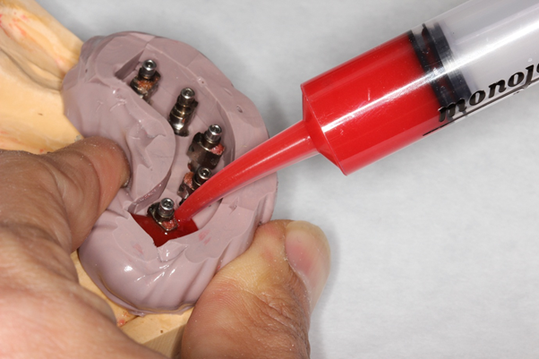
Auto-polymerizing acrylic resin (Pattern Resin LS; GC America, Alsip, IL) was used to splint the impression copings. To ensure that the same amount of material was used to fabricate the splint, a pre-determined volume and ratio of powder and liquid was used (10 grams of powder and 6 ml of liquid). The powder and liquid were mixed for 30 seconds until the mixture was homogenous. The mixture was then poured into a plastic syringe (Monoject; Medtronic, Fridley, MN), injected into the matrix, and allowed to polymerize undisturbed according to the assigned time group (8 MN, 1 HR, and 24 HR). (Figures 1-2) After the assigned time lapsed, the splinted impression copings were removed from the definitive cast along with the matrix.
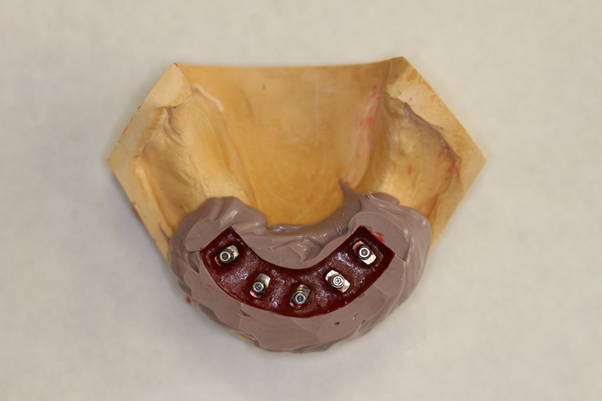
Figure 2: The acrylic mixture was allowed to polymerize undisturbed according to the assigned time groups.
For the sectioned groups (8 MN-S, 1 HR-S, and 24 HR-S), the splinted impression copings were sectioned with a diamond disc (Brasseler; Savannah, GA). They were then re-positioned on the implant analogs in the definitive cast without the PVS matrix. The sectioned pieces were re-luted with auto-polymerizing acrylic resin (Pattern Resin LS) through the brush technique. The added acrylic resin was allowed to polymerize for 8 minutes on the definitive cast before the splinted impression copings were removed.
Once the polymerization times were complete for both the non-sectioned and sectioned groups, the impression copings were connected to implant lab analogs (3i Implant Innovations). Type IV dental stone (Whipmix Combination Unit; Louisville, KY) was mixed with distilled water (Kandiyohi Bottled Water Company; Willmar, MN) at the manufacturer recommended water/powder ratio and vacuum spatulated using a mechanical spatulator (Whipmix Combination Unit; Louisville, KY). The mixed stone was poured into a silicone model base former (US Dental Depot; Fort Lauderdale, FL) and the combined splinted impression coping-implant analog units were inserted into the stone mixture by pushing firmly to full depth.
The dental stone was allowed to polymerize for one hour and then the casts were removed from the model base former. The splinted impression copings were removed from the implant analogs and were reused throughout the experiment. The procedures were continued until 20 casts were made for each time group (8 MN, 1 HR, and 24 HR), with 10 casts for the sectioned group (S) and another 10 for the non-Sectioned group (NS), for a total 60 casts. The experimental casts were labeled according to their group along with a sample number to prepare for measurements.
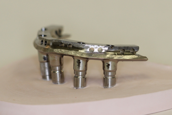
All 60 experimental casts were evaluated independently by placing the milled titanium bar on the implant analogs for each experimental cast. (Figure 3) The one-screw test was performed where one screw was placed in the area of the furthest left implant site (labeled implant 0) to secure the milled titanium bar in place. The remaining implant sites were labeled from 1 to 4, with 4 being the most distal implant on the right side.
Visual inspection under 2.5x magnification loupes (Q-Optics; Duncanville, TX) along with tactile sensation with a new 50 µm tip dental explorer (Hu Friedy USA; Chicago, IL) was completed to detect a gap at the remaining 4 implant positions. To be considered a clinical fit, a smooth transition had to be present when the dental explorer passed over the prosthesis-implant analog junction. With a 50 µm tipped dental explorer, any gaps smaller than 50 µm were not detected and the connection was considered a fit while any gaps larger than 50 µm were detected by a catch of the explorer and the connection was considered a misfit. If all 4 of the tested implant bar-analog connections had a smooth transition, the sample was considered a clinical fit. On the contrary, if one or more of the implant sites had a detectable gap, the sample was considered a clinical misfit.
Additional visual inspection under 12.8x magnification microscope (Global G3 Series; Global Surgical Corporation, Saint Louis, MO) was done to get a better visualization of the gaps present as well as to detect any gaps smaller than 50 µm that were undetected in the previous step. (Figures 4a-c)
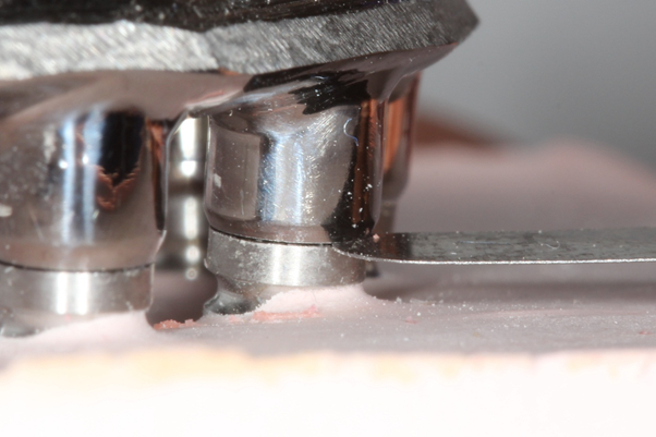
A measuring gauge (Jinghua; China) with pre-determined thickness in microns (μm) was used to measure the gap size at each implant’s position. (Figure 5) The visible gap and corresponding gap size for each site were recorded on a spreadsheet in an XLS (Excel) file.
For the statistical analysis, a spreadsheet in an XLS file was created with the gap positions and gap sizes recorded, as well as the fit evaluation. Fisher’s exact test was used to analyze the fit frequency between each group. In addition, univariate exact logistic regression was used to estimate the odds ratio of the qualitative results (fit and not-fit samples) between the groups. Wilcoxon rank test was also used to analyze the number of gaps present between each experimental group. A p-value of < 0.05 was considered significant.
Results
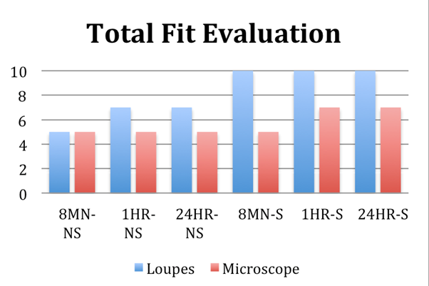
The implant-bar connections in each sample underwent fit evaluation, which was determined by evaluating whether a gap was present. If any implant site had a gap present, it was considered a misfit. When viewed with magnification loupes, all of the samples in the Sectioned groups displayed total fit. Conversely, when viewed with a microscope, there were fewer samples that showed absolute fit. (Figure 6)
Fewer samples with absolute fit seen with the microscope are due to the magnification loupes and dental explorer being unable to detect gaps that are smaller than 50 µm. Although the clinical evaluation methods utilized in this study (visual and tactile sensation) showed a higher number of samples with clinical fit, it can be concluded that an absolute fit could not be achieved on all samples.
Fisher’s exact test was used to perform statistical comparison between the different groups in regards to clinical fit as detected with magnification loupes and a dental explorer. (Table 1) When comparing the different polymerization times on the accuracy of clinical fit, the differences between each time group were not statistically significant.
| Section | Time | Fit Frequency, n (%) | p-value | Odds Ratio (95% CI) |
| Yes | 8 min vs. 1 hr | 10 (100) vs. 10 (100) | >.99 | NA |
| 8 min vs. 24 hr | 10 (100) vs. 10 (100) | >.99 | NA | |
| 1 hr vs. 24 hr | 10 (100) vs. 10 (100) | >.99 | NA | |
| No | 8 min vs. 1 hr | 5 (50) vs. 7 (70) | 0.6499 | 0.43 (0.07, 2.68) |
| 8 min vs. 24 hr | 5 (50) vs. 7 (70) | 0.6499 | 0.43 (0.07, 2.68) | |
| 1 hr vs. 24 hr | 7 (70) vs. 7 (70) | >.99 | 1.00 (0.15, 6.77) | |
| Yes vs. No | 8 min | 10 (100) vs. 5 (50) | 0.0325 | NA |
| Yes vs. No | 1 hr | 10 (100) vs. 7 (70) | 0.2105 | NA |
| Yes vs. No | 24 hr | 10 (100) vs. 7 (70) | 0.2105 | NA |
Table 1: Statistical comparison of fit frequency between different groups (loupes).
Likewise, when comparing the sectioned and non-sectioned samples for each specific time group, no statistical significance was found between the sectioned and non-sectioned samples of the 1-hour and 24-hour time groups. However, a statistically significant difference is seen within the 8-minute time groups (p-value = 0.0325). This shows that there is a difference in the clinical fit frequency when sectioning is involved for impression copings that are splinted for 8 minutes, sectioned, and re-luted.
Similarly, Fisher’s exact test was also used for statistical comparison between the different groups in regards to fit as detected with the microscope. (Table 2) Unlike the data gathered by evaluating with magnification loupes, there were no statistical differences between any of the sectioned and non-sectioned samples for each time group when evaluating with a microscope. The data reveals that the microscope is capable of detecting gaps that were undetectable with just the magnification loupes and a dental explorer, particularly with the sectioned groups.
| Section | Time | Fit Frequency, n (%) | p-value | Odds Ratio (95% CI) |
| Yes | 8 min vs. 1 hr | 5 (50) vs. 7 (70) | 0.65 | 0.43 (0.07, 2.68) |
| 8 min vs. 24 hr | 5 (50) vs. 7 (70) | 0.65 | 0.43 (0.07, 2.68) | |
| 1 hr vs. 24 hr | 7 (70) vs. 7 (70) | >.99 | 1.00 (0.15, 6.77) | |
| No | 8 min vs. 1 hr | 5 (50) vs. 5 (50) | >.99 | 1.00 (0.17, 5.77) |
| 8 min vs. 24 hr | 5 (50) vs. 5 (50) | >.99 | 1.00 (0.17, 5.77) | |
| 1 hr vs. 24 hr | 5 (50) vs. 5 (50) | >.99 | 1.00 (0.17, 5.77) | |
| Yes vs. No | 8 min | 5 (50) vs. 5 (50) | >.99 | 1.00 (0.17, 5.77) |
| Yes vs. No | 1 hr | 7 (70) vs. 5 (50) | 0.65 | 2.33 (0.37, 14.61) |
| Yes vs. No | 24 hr | 7 (70) vs. 5 (50) | 0.65 | 2.33 (0.37, 14.61) |
Table 2: Statistical comparison of fit frequency between different groups (microscope).
In regards to the number of gaps detected with magnification loupes and a dental explorer, Wilcoxon rank test was used to perform statistical comparison. (Table 3) When comparing the number of gaps between the different polymerization time groups, no statistically significant differences were detected between them. On the contrary, when comparing the effects of sectioning on the number of gaps in their respective polymerization time groups, a statistical significance was seen within the 8-minute time group. (P-value = 0.02) This indicates that sectioning the splinted impression copings after 8 minutes can reduce the amount of gaps at the prosthesis-bar interface.
| Magnification Loupes | Microscope | |||||
| Section | Time | p-value | Section | Time | p-value | |
| Yes | 8 min vs. 1 hr vs. 24 hr | NA | Yes | 8 min vs. 1 hr vs. 24 hr | 0.53 | |
| No | 8 min vs. 1 hr vs. 24 hr | 0.57 | No | 8 min vs. 1 hr vs. 24 hr | >.99 | |
| Yes vs. No | 8 min | 0.02 | Yes vs. No | 8 min | 0.66 | |
| Yes vs. No | 1 hr | 0.09 | Yes vs. No | 1 hr | 0.25 | |
| Yes vs. No | 24 hr | 0.09 | Yes vs. No | 24 hr | 0.25 | |
Table 3: Statistical comparison of number of gaps between different groups.
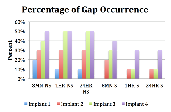
Furthermore, the percentage of gaps occurring for each implant position in the respective time group is reflected in Figure 8. Similar to the mean gap size trend, the most distal implant (Implant 4) had the highest percentage of gaps occurring in all time groups, while the lowest percentage of gap occurrence was at Implant 1.
Discussion
The data supports the acceptance of the first null hypothesis; that there is no difference between different polymerization times. The data also partially rejects the acceptance of the second null hypothesis; that there is no difference between sectioning and not sectioning. As the results show, the differences between each polymerization time group are not significantly different, while the only statistically significant difference between the sectioned and not sectioned samples was seen between the 8-minute time groups (p-value = 0.0325).
Passive fit, or ideal fit, has been reported to be a significant prerequisite in maintaining the bone-implant interface and not producing any strain on the supporting implants and surrounding hard tissue. [1] It is imperative that an accurate transfer from the oral environment to the laboratory setting is achieved in order to lower the probable distortion that may happen. [2]
For the purpose of this investigation, which is to evaluate the effects of different polymerization times and sectioning of splinting material, impression material was not used to eliminate it being a possible source for additional distortion. Moreover, the same splinting and investment materials were used for all sample groups.
Auto-polymerizing acrylic resin was chosen because it is a widely used material for splinting impression copings with good accuracy and low shrinkage. It can also be shaped and manipulated easily to control the consistency and flow of the material. In order to standardize the amount of material used, a pre-determined amount of powder and liquid was mixed and a matrix made from heavy-body PVS was utilized to act as a reservoir during polymerization.
When evaluating clinical fit of the titanium bar on the experimental casts with magnification loupes and a dental explorer, all of the samples that were sectioned exhibited clinical fit, meaning that none of the implants had detectable gaps. Although the effect of polymerization time on fit was not significant, sectioning did show to have a substantial impact for the 8-minute time group (p = 0.0325). These findings demonstrate that the first null hypothesis regarding polymerization time is not rejected, while the second null hypothesis regarding sectioning is partially rejected as the 8-minute time group showed significant difference between the sectioned and non-sectioned samples.
Yet, when a microscope was used to evaluate the connections, absolute fit was not seen in all of the sectioned samples as it was with the magnification loupes. This demonstrates that although “clinical” fit appears to be present, there is still a degree of misfit that could not be detected with methods used clinically, e.g. visual and tactile method. Whether this degree of misfit has an effect on the forces created around the implants is a subject for further investigation.
The results are corroborated when comparing the number of gaps between the different experimental groups. There is significant statistical correlation (p = 0.02) between sectioning and not sectioning for the 8-minute time group when viewed under magnification loupes while no other statistical differences are seen in the remaining groups. Despite the lack of a statistical association, there appears to be a trend where fewer gaps are detected in the sectioned samples when compared with their respective non-sectioned counterparts under a microscope.
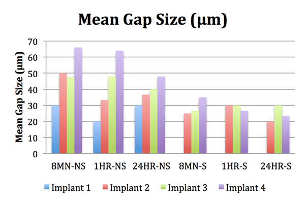
Further evaluation with a measuring gauge under a microscope was done to measure the gap size at each implant position. An overall pattern can be appreciated where the most distal implant (Implant 4) mostly had the highest mean gap size and always had the highest percentage of gap occurrence for each respective group. Meanwhile, Implant 1 (the closest implant to the implant with the prosthetic screw) always had the lowest, if any, mean gap size and percentage of gap occurrence.
A pattern can also be seen between the sectioned and non-sectioned groups, where the overall mean gap sizes were smaller in the sectioned group when compared with the latter. In a study by Papaspyridakos (2012) [45], it was concluded that a maximum range of discrepancy or misfit between 59 to 72 µm still resulted in a clinical fit with one-piece implant-supported prostheses. The mean gap sizes calculated in the current study were all within this range while only 3 samples had a measured gap size larger than this value, all of which were at the most distal implant.
The results from this research partially supports a study performed by Cerqueira (2012) [44], where no differences were seen between splinted impression copings using Pattern Resin LS that were not sectioned, sectioned and reconnected after 17 minutes, and sectioned and reconnected after 24 hours. Cerqueira also reported that the amount of microstrain values from the Pattern Resin LS groups were all below the lowest value from the other tested material, Duralay II. It appears that as long as a low-shrinking material is used, sectioning and polymerization time does not have an effect on reducing the amount of distortion.
Cerqueira’s study is only partially supported because in the present study, a significant difference was observed between the different techniques for the 8-minute time group. This time group was not a part of the former’s experimental groups, so it could not be fully compared. Mojon (1990) [38] reported that acrylic resin undergoes 80% of shrinkage within the first 17 minutes while no critical dimensional changes are evident after 24 hours. It can be concluded that if impression copings are to be initially splinted with acrylic resin for only 8 minutes, it should be sectioned and reconnected.
The results from this study also supports statements made by Sahin (2001) [1] and Wee (1999) [2] that absolute fit cannot always be achieved as there will always be some source of error. It is in the dentist’s best interest to eliminate as much of the prospective error as possible and fabricate a prosthesis that does not induce any stress when seated on the implants.
Limitations to the current study include small sample size and impression copings that may not be fully seated when connecting to an implant analog or when connecting to the master cast due to the matrix being in place. It is possible that the matrix could interfere with proper seating of the impression copings, but when it was reconnected after sectioning, that they could be fully seated since the matrix was not used at that point. This could be a reason as to why there were fewer detectable gaps in the sectioned groups. In the clinical setting, this would be avoided since no matrix will be used intraorally and radiographs are often taken to verify the complete seating of the impression copings.
Another source of error could be introduced from the mixing ratio of the auto-polymerizing acrylic resin. Most practitioners tend to utilize the brush technique where portions of acrylic are added along a scaffold of dental floss with a brush soaked in monomer picking up the polymer. [31,39] For the purpose of this study, a pre-determined powder to liquid ratio of acrylic resin mixed together was used to keep the amount of acrylic resin standardized. In order for the mixed acrylic to flow and fill the space provided by the matrix, an excess amount of liquid monomer was needed to give the fluid properties. Also, the bulk of the splinted acrylic resin created with the matrix was larger than if a scaffold is used for the brush & dip technique. These modifications to the procedure could result in more shrinkage and distortion due to the higher amount of liquid and the larger bulk of material.
Future research is needed to determine the effects of prosthesis misfit on the surrounding structures, as this study demonstrated that absolute fit is not always achievable. Additionally, 3-dimensional technology, such as scanning and overlapping the scanned data, and a strain gauge can be utilized to aid in evaluating the potential clinical consequences of such deviation. This information would be highly beneficial in determining how much of a misfit may be considered clinically acceptable without causing any harm to the implants or bone.
Conclusion
Within the limitations of this study, the following conclusions were drawn:
- There were no statistically significant differences between experimental casts generated with different splint polymerization times, and between sectioned and non-sectioned samples of the 1-hour and 24-hour time groups.
- There were statistically significant differences between the sectioned and non-sectioned samples of the 8-minute time group when evaluated with the visual and tactile method (magnification loupes and a dental explorer). When viewed under the microscope, however, there were no statistically significant differences.
- Although clinical fit was present after evaluating with the visual and tactile method, it did not automatically mean that absolute fit was present when viewed under a microscope.
- The most distal implant had the highest mean gap size and percentage of gap occurrence.
- Sectioning resulted in smaller mean gap sizes.
References
- Sahin S and Cehreli MC. "The significance of passive framework fit in implant prosthodontics: Current status". Implant Dentistry 10.2 (2001): 85-92.
- Wee AG., et al. "Strategies to achieve fit in implant prosthodontics: A review of the literature”. The International Journal of Prosthodontics 12.2 (1999): 167-178.
- Skalak R. "Biomechanical considerations in osseointegrated prostheses”. The Journal of Prosthetic Dentistry 49.6 (1983): 843-848.
- Adell R., et al. "A 15-year study of osseointegrated implants in the treatment of the edentulous jaw”. International Journal of Oral Surgery 10.6 (1981): 387-416.
- Jemt T and Book K. "Prosthesis misfit and marginal bone loss in edentulous implant patients”. The International Journal of Oral & Maxillofacial Implants 11.5 (1996): 620-625.
- Jemt T. "In vivo measurements of precision of fit involving implant-supported prostheses in the edentulous jaw”. The International Journal of Oral & Maxillofacial Implants 11.2 (1996): 151-158.
- Kallus T and Bessing C. "Loose gold screws frequently occur in full-arch fixed prostheses supported by osseointegrated implants after 5 years”. The International Journal of Oral & Maxillofacial Implants 9.2 (1994): 169-178.
- Jemt T. "Failures and complications in 391 consecutively inserted fixed prostheses supported by branemark implants in edentulous jaws: A study of treatment from the time of prosthesis placement to the first annual checkup”. The International Journal of Oral & Maxillofacial Implants 6.3 (1991): 270-276.
- Carr AB., et al. "The response of bone in primates around unloaded dental implants supporting prostheses with different levels of fit”. The Journal of Prosthetic Dentistry 76.5 (1996): 500-509.
- Kunavisarut C., et al. "Finite element analysis on dental implant-supported prostheses without passive fit”. Journal of Prosthodontics: Official Journal of the American College of Prosthodontists 11.1 (2002): 30-40.
- Abduo J and Judge RB. "Implications of implant framework misfit: A systematic review of biomechanical sequelae”. The International Journal of Oral & Maxillofacial Implants 29.3 (2014): 608-621.
- Winter W., et al. "Bone adaptation induced by non-passively fitting implant superstructures: A finite element analysis based on in vivo strain measurements”. The International Journal of Oral & Maxillofacial Implants 26.6 (2011): 1288-1295.
- Natali AN., et al. "Investigation of bone inelastic response in interaction phenomena with dental implants”. Dental Materials: Official Publication of the Academy of Dental Materials 24.4 (2008): 561-569.
- Spazzin AO., et al. "Effects of horizontal misfit and bar framework material on the stress distribution of an overdenture-retaining bar system: A 3D finite element analysis”. Journal of Prosthodontics: Official Journal of the American College of Prosthodontists 20.7 (2011): 517-522.
- Kallus T and Bessing C. "Loose gold screws frequently occur in full-arch fixed prostheses supported by osseointegrated implants after 5 years”. The International Journal of Oral & Maxillofacial Implants 9.2 (1994): 169-178.
- Wennerberg A and Jemt T. "Complications in partially edentulous implant patients: A 5-year retrospective follow-up study of 133 patients supplied with unilateral maxillary prostheses”. Clinical Implant Dentistry and Related Research 1.1 (1999): 49-56.
- Bacchi A., et al. "Loosening torque of prosthetic screws in metal-ceramic or metal-acrylic resin implant-supported dentures with different misfit levels”. Journal of Biomechanics 46.7 (2013): 1358-1362.
- Jokstad A and Shokati B. "New 3D technologies applied to assess the long-term clinical effects of misfit of the full jaw fixed prosthesis on dental implants”. Clinical Oral Implants Research 26.10 (2015): 1129-1134.
- Branemark PI. "Osseointegration and its experimental background”. The Journal of Prosthetic Dentistry 50.3 (1983): 399-410.
- Klineberg IJ and Murray GM. "Design of superstructures for osseointegrated fixtures”. Swedish Dental Journal.Supplement 28 (1985): 63-69.
- Ma T., et al. "Tolerance measurements of various implant components”. The International Journal of Oral & Maxillofacial Implants 12.3 (1997): 371-375.
- Kan JY., et al. "Clinical methods for evaluating implant framework fit”. The Journal of Prosthetic Dentistry 81.1 (1999): 7-13.
- Abduo J., et al. "Assessing the fit of implant fixed prostheses: A critical review”. The International Journal of Oral & Maxillofacial Implants 25.3 (2010): 506-515.
- Daoudi MF., et al. "A laboratory investigation of the accuracy of two impression techniques for single-tooth implants”. The International Journal of Prosthodontics 14.2 (2001): 152-158.
- Carr AB. "Comparison of impression techniques for a five-implant mandibular model”. The International Journal of Oral & Maxillofacial Implants 6.4 (1991): 448-455.
- Conrad HJ., et al. "Accuracy of two impression techniques with angulated implants”. The Journal of Prosthetic Dentistry 97.6 (2007): 349-356.
- Lee H., et al. "The accuracy of implant impressions: A systematic review”. The Journal of Prosthetic Dentistry 100.4 (2008): 285-291.
- De La Cruz JE., et al. "Verification jig for implant-supported prostheses: A comparison of standard impressions with verification jigs made of different materials”. The Journal of Prosthetic Dentistry 88.3 (2002): 329-336.
- Branemark PI., et al. Albrektsson. Tissue-Integrated Prostheses: Osseointegration in Clinical Dentistry. Chicago: Quintessence Publishing, 1985. Print.
- Assif D., et al. "Accuracy of implant impression splinted techniques: Effect of splinting material”. The International Journal of Oral & Maxillofacial Implants 14.6 (1999): 885-888.
- Rutkunas V and Ignatovic J. "A technique to splint and verify the accuracy of implant impression copings with light-polymerizing acrylic resin”. The Journal of Prosthetic Dentistry 111.3 (2014): 254-256.
- Del'Acqua MA., et al. "Accuracy of impression techniques for an implant-supported prosthesis”. The International Journal of Oral & Maxillofacial Implants 25.4 (2010): 715-721.
- Windhorn RJ and Gunnell TR. "A simple open-tray implant impression technique”. The Journal of Prosthetic Dentistry 96.3 (2006): 220-221.
- Hariharan R., et al. "Evaluation of accuracy of multiple dental implant impressions using various splinting materials”. The International Journal of Oral & Maxillofacial Implants 25.1 (2010): 38-44.
- Carr AB and Master J. "The accuracy of implant verification casts compared with casts produced from a rigid transfer coping technique”. Journal of Prosthodontics: Official Journal of the American College of Prosthodontists 5.4 (1996): 248-252.
- Filho HG., et al. "Accuracy of impression techniques for implants. Part 2 - comparison of splinting techniques”. Journal of Prosthodontics: Official Journal of the American College of Prosthodontists 18.2 (2009): 172-176.
- "GC Pattern Resin LS low shrinkage modeling resin tips and tricks: Technique and handling of GC Pattern Resin”. 2009. Web.
- Mojon P., et al. "Polymerization shrinkage of index and pattern acrylic resins”. The Journal of Prosthetic Dentistry 64.6 (1990): 684-648.
- Gibbs SB., et al. "Comparison of polymerization shrinkage of pattern resins”. The Journal of Prosthetic Dentistry 112.2 (2014): 293-298.
- Dumbrigue HB., et al. "Prefabricated acrylic resin bars for splinting implant transfer copings”. The Journal of Prosthetic Dentistry 84.1 (2000): 108-110.
- Spector MR., et al. "An evaluation of impression techniques for osseointegrated implants”. The Journal of Prosthetic Dentistry 63.4 (1990): 444-447.
- Moon PC., et al. "Comparison of accuracy of soldering indices for fixed prostheses”. The Journal of Prosthetic Dentistry 40.1 (1978): 35-38.
- Ivanhoe JR., et al. "An impression technique for osseointegrated implants”. The Journal of Prosthetic Dentistry 66.3 (1991): 410-411.
- Cerqueira NM., et al. "A strain gauge analysis of microstrain induced by various splinting methods and acrylic resin types for implant impressions”. The International Journal of Oral & Maxillofacial Implants 27.2 (2012): 341-345.
- Papaspyridakos P., et al. "Accuracy of implant casts generated with splinted and non-splinted impression techniques for edentulous patients: An optical scanning study”. Clinical Oral Implants Research 23.6 (2012): 676-681.
Citation:
Jason P Kiangsoontra and Heather J Conrad. “Comparison of the Dimensional Stability of Splinting Material with Different
Polymerization Times”. Oral Health and Dentistry 1.4 (2017): 197-209.
Copyright: © 2017 Jason P Kiangsoontra and Heather J Conrad. This is an open-access article distributed under the terms of the Creative Commons Attribution License, which permits unrestricted use, distribution, and reproduction in any medium, provided the original author and source are credited.



















 Scientia Ricerca is licensed and content of this site is available under a Creative Commons Attribution 4.0 International License.