Conceptual Paper
Volume 3 Issue 4 - 2018
Making Artificial Gum on Bio-stereolithographic Models in the Diagnosis and Prosthetic Implant-assisted Planning
1Professor Graduate School of Periodontics and Implant Dentistry. Faculty of Dentistry, De los Andes University, Santiago, Chile
2Private practice at Clínica Odontológica San Sebastian, Santiago, Chile
2Private practice at Clínica Odontológica San Sebastian, Santiago, Chile
*Corresponding Author: Yerko Leighton, Private practice at Clínica Odontológica San Sebastian, Santiago, Chile.
Received: June 19, 2018; Published: June 25, 2018
Abstract
Purpose: The purpose of this report is to describe three methods for making artificial gum on stereo lithographic bio models, for diagnosis and treatment planning in implant assisted prosthetics.
Methods: The protocol was developed in a group of 18 subjects with edentulous jaws, which required prosthetic implant assisted treatment. The subjects were divided in three groups.
Group A: Electronic Manufacture of soft gum (6 models).
Group B: semi electronic Manufacture of soft gum (6 models).
Group C: Preparation by manual mapping of soft gum (6 models).
Group B: semi electronic Manufacture of soft gum (6 models).
Group C: Preparation by manual mapping of soft gum (6 models).
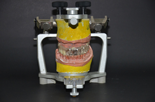
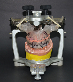
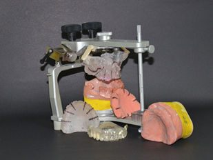
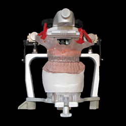
With all the gums made, the models were mounted on semi adjustable articulator to continue their diagnosis and treatment plan in implant assisted prosthetics.
Results: A total of 18 artificial gums were prepared, in 3 groups of 6 models pero group, which were extremely useful for the development, implementation and prognosis of implant assisted treatment of the patient.
Conclusions: With the limitations of this report, diagnosis, planification and indication of dental implants, using bio stereo lithographic models mounted in semi-adjustable articulator, facilitates and optimizes the diagnosis and treatment of patients with implant assisted prosthetic by minimizing the surgical risks.
Key words: Bio models; Stereo lithography; Implants
Introduction
During the diagnostic phase and prosthetic treatment planning, it is essential to acquire the necessary tools in order to optimize aesthetics, function and prognosis of implant supported restorations. One of the greatest difficulties of implant-assisted treatment is the ability to link the prosthetic planning with the surgical planning, thus, the insertion of implants must be first conceived from the prosthetic point of view and not from bone availability [1,2]. Angulation problems and tilt implants are often difficult to solve in both single and full arch restorations [3-6]. This is why local anatomical situations generate the necessity of choosing an ideal diagnostic method, trustworthy and reliable, enabling both surgical and prosthetic planning [3,5], obtaining clear and accurate inofmacion of noble structures for implantology, such the route of the inferior alveolar nerve, the location of the maxillary sinus and the ability to deliver vital information from adjacent pathology areas.
During the process of complementary exams and treatment planning there are tools that help the interpretation of the images. These tools are radiographic guides, which are a the complement that should always be considered when an imaging exam is requested, and after that, this devices can be transformed or can help to originate surgical guides, which can be not strict and strict .Without doubt, strict surgical guides are those that provide the best performance in the implant positioning, facilitating the surgical sequence and disabling the change of direction of insertion [7-17].
In the progress and development of implantology Dr. Daniel Van Steenberghe with his team, designed a computer system capable of doing surgical implant planning, making strict surgical guides with the chance of making a screw retained prosthesis placed in the patient immediately after the surgery is completed. All these computer made components arrive directly from the manufacturer [1]. (Nobel Guide, Nobel Biocare, Goteborg, Sweden). The analysis of this latest system is based on information acquired by the CT scan, interpretation of DICOM files, and materialization achieved by the stereo lithography [17].
The use of bio stereo lithographic models based on CT scans have been used since about 20 years ago, in the manufacture of subperiosteal implants, thus avoiding surgical impressions [17,18]. Cranin., et al. [19]Compared implant direct impressions and the accuracy of the bio stereo lithographic models in the manufacture of sub periosteal implants, Mc Allister [18] suggests excellent fidelity and accuracy of the bio models reproducing anatomy and anatomic landmarks for the insertion of subperiosteal implants.
The bio stereo lithographic models are real scale sized and the clinician can identify critical areas in implantology, such as, the inferior alveolar nerve, the maxillary sinuses and nasal passages in the insertion of implants [16]. Vrielinck., et al.[20] Recommended the use of bio stereo lithographic models in the treatment of severely resorbed jaws in order to optimize implant sites such as zygomatic bones and pterygoid processes. The use of CT scan and construction of bio models support both treatment planning and the construction of strict surgical guides, enabling to optimize implant positioning, reducing surgical risks and time in the operating room.
The purpose the present study is to recreate the function of a dental prosthesis with the bone model of the patient in bio stereo lithographic relating it through the making of artificial gingiva in order to realizer the mount in the articulator to realizer a correct diagnosis and prosthetic implant treatment.
Materials and Methods
18 patients were selected, of which 6 already had a dental scan requested by another dentist. The rest of the subjects were divided in 2 groups of 6 and were prepared for CT scans. All of them met the inclusion criteria and were informed of the diagnostic procedure that would be implemented, and asked to sign an informed consent.
The inclusion criteria for this type of treatment were
- Older than 18 years.
- Absence of systemic alterations that contraindicate implant surgery.
- Clinical laboratory values compatible with implant surgery. (Complete blood count, glycemia, coagulation time, sedimentation rate).
Work groups
Group A: electronic manufacture of soft gum (6 models)
Group B: semi electronic manufacture of soft gum (6 models)
Group C: manual mapping manufacture of soft gum (6 models).
Group A: electronic manufacture of soft gum (6 models)
Group B: semi electronic manufacture of soft gum (6 models)
Group C: manual mapping manufacture of soft gum (6 models).
Prosthetic phase: Group A and Group B
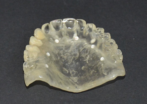
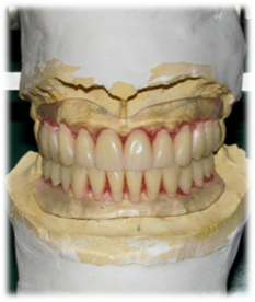
The protocol begins with an alginate impression to obtain cast models, which were articulated in a semi adjustable articulator (Bio Art, articulator) using height impellers according to the facial biotype of the patients. With this information, the dental laboratory constructs a tooth wax-up to be tried in the patient, after which, the laboratory proceeds to transform this into thermal polymerization acrylic resin. Once the prosthesis is finished, proceeds to duplicate it in transparent acrylic resin, which must be rigid and very adapted to the gum, relined if necessary with translucent acrylic resin, in order to form the radiographic guides which are marked with 6 palatal gutta-percha markers of 1 mm diameter.
The protocol begins with an alginate impression to obtain cast models, which were articulated in a semi adjustable articulator (Bio Art, articulator) using height impellers according to the facial biotype of the patients. With this information, the dental laboratory constructs a tooth wax-up to be tried in the patient, after which, the laboratory proceeds to transform this into thermal polymerization acrylic resin. Once the prosthesis is finished, proceeds to duplicate it in transparent acrylic resin, which must be rigid and very adapted to the gum, relined if necessary with translucent acrylic resin, in order to form the radiographic guides which are marked with 6 palatal gutta-percha markers of 1 mm diameter.
With this guide in oral MIC position, patient proceeds to the take the scanner, then the radiographic guide with gutta-percha markers is scanned itself. Both scanners are fused into a digital design program (Materialice, Mimics) and from there required images are generated.
Prosthetic phase: Group C
In this group of patients brought their scanner which were requested previously by another dentist, so proceeded to the confection the radiographic guide the same way as the other two groups to get their acrylic prosthesis and process the scanner images for making bio bone models.
In this group of patients brought their scanner which were requested previously by another dentist, so proceeded to the confection the radiographic guide the same way as the other two groups to get their acrylic prosthesis and process the scanner images for making bio bone models.
Method of making artificial gingiva
Group A: electronics Manufacture of artificial gum
Group A: electronics Manufacture of artificial gum
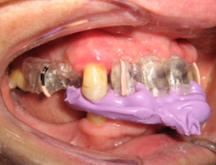
- Take a scanner to the patient with a radiographic guide in the mouth stabilized with rigid bite registration. (Figure 1, Figure 3)
- Take a scanner to the radiographic guide. (Figure 2)
- Merge both images electronically as matching electronic overlay markers of the radiographic guide. (Figure 4)
- The merge creates an electronic space which is the patient's gums.
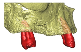
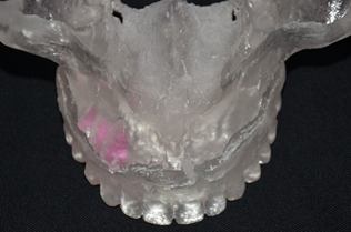
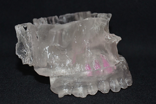
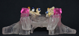
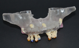
- Request the laboratory to make gum in soft stereolithography and bone in hard stereolithography. (Figure 5 to 9)
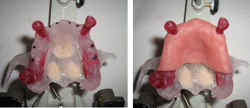
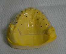
Figure 5 and 6: Hard stereo lithography for superior maxillary bone and soft stereo lithography for artificial gum.
Group B: Semi-electronics manufacture of artificial gum
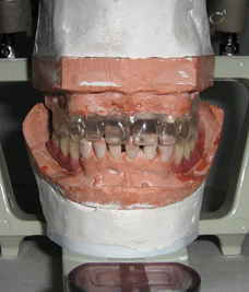
- Models are mounted in the articulator. Then a scanner is taken to the patient with a radiographic guide in the mouth stabilized with rigid bite registration. (Figure 10)
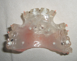
- Take a scanner to the radiographic guide. (Figure 11)
- Merge both images electronically as matching electronic overlay markers of the radiographic guide.
- The merge creates an electronic space which is the patient's gums. (Figure 12 and 13)
- Four attaches are electronically generated so that they match the prosthesis and the maxillary bone. Then a stereo lithographic bio model is requested with both structures fused, a bone and prosthesis bio model.
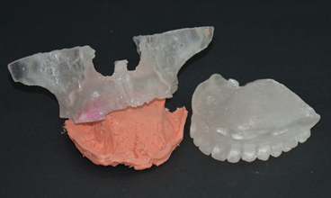
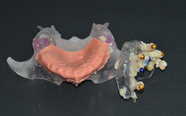
- The space between the maxillary stereolithography and the stereolithography copy of the attached prosthesis is filled with silicone gum in the dental laboratory. (Figure 14)
- Proceed to cutting and separation of both stereolithography structures, obtaining the bone sterelithography and artificial gum formed. (Figure 15 and 16)
Group C: Manual manufacture of artificial gum using bone mapping method
The development of this protocol is based on a manual work of the dentist, because the patient has a scanner that was requested by another colleague or was requested without compliance with the protocol described in the previous cases. The aim is to be able to obtain the same benefits of diagnosis and treatment of previous cases.
The development of this protocol is based on a manual work of the dentist, because the patient has a scanner that was requested by another colleague or was requested without compliance with the protocol described in the previous cases. The aim is to be able to obtain the same benefits of diagnosis and treatment of previous cases.
The protocol is based on obtaining a 3D volume of the patient's bone obtained by the DICOM files, it is exported to an STL file and printed on the stereo lithography technique. In parallel, a rigid stamping of the entire covering of the maxillary gingiva is made as if it were a total prosthesis covering, which is the one who performs the topography of the patient's gingiva from a minimum of 4 Metal stops attached to the acrylic print. The purpose of the metal stops is to make bone contact, thereby we can define the thickness of the gingiva of the palate in addition to using at least 4 points in order to achieve polygonal stability. Once fixed the points this is removed from the mouth and is mounted on the 3D bone model taking care to produce this polygonal stability of bone support, then fixed with acrylic and introduces fluid self-mixing by gun and a fine cannula.
The following is the step-by-step protocol:
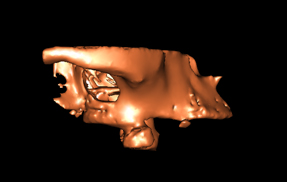
- Requested stereolithography bone model (only the maxillary bone). (Figure 17)
- A maxillary impression of the patient is taken, which is cast in super firm. Then, the limits of a conventional complete denture are demarcated in the cast model with a pencil.
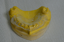
- Proceed to make a vacuum print pressed with a rigid non-flexible sheet, cut according to the definition made by the pencil.
- Test the fit and stability on the mucosa of the patient. (Figure 18)
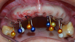
- Drill stamped with a minimum of 10 points that allow a polygonal stability, three in occlusal by hemiarch and four palatal. (Figure 19 and 20)
- Anesthetize the mucosa.
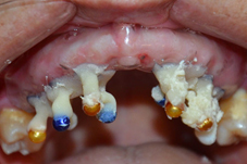
- By metal caps pierce the mucosa until running into bone. (Figure 21)
- Bind metal caps to each other and to the stamped base using Duralay acrylic resin. (Figure 22)
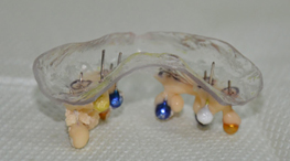
- Remove from mouth, wash, dry and place on the stereo lithography making sure that all the metal caps have bone contact, then fix the transparent vacuum print to the stereolithography model using acrylic resin. (Figure 23 to 26)
- The space generated between the model and the stereolithographic model is filled with silicone gum in the laboratory, to form the artificial gum. (Figure 27)
Conclusion
With the limitations of this report, we can say that the use of stereo lithographic bio models facilitate and improve the treatment planning and execution of implant positioning and reconstructive surgery, providing the possibility of making devices like surgical and bone cutting guides, modeling titanium mesh. These methods also provide the surgeon the option of performing a simulated surgery, identificating the advantages and disadvantages of each procedure. These are also is a mean of relationship and explanation to the patient and a mean of communication between the surgeon and the prosthodontist.
Conflict of interest
No conflict of interest exists.
No conflict of interest exists.
References
- Daniel van Steenberghe., et al. “A Custom Template and Definitive Prótesis Aliowing Immediate implant Loading in the Maxilla: A Clinical Report”. The International Journal of Oral & Maxillofacial Implants 17.5 (2002): 663-670.
- Misch CM. “Bur guide surgical template for implant placement in grafted jaws”. Journal of Oral Implantology 23.4 (1997): 170-173.
- Roger Minorctti and Beat R Merz. “Albino Triacal Predeterrnined implant positioning by means of a novel guide template technique”. Clinical Oral Implants Research 11 (2000): 266-272.
- Misch CM. “Bur guide surgical template for implant placement in grafted jaws”. Journal of Oral Implantology 23.4 (1997): 170-173.
- Philippe B Tardieu., et al. “Computer-assisted lmplant Placernent. A Case Report: Treatment of the Mandible”. The International Journal of Oral & Maxillofacial Implants 18.4 (2003): 599-604.
- Cowan PW. “Surgical templates for the placement of osseointegrated implants”. Quintessence International 21.5 (1990): 391-396.
- SCOTT D GANZ. “CT Scan Technology an Evolving Tool for Avoiding Complications and Achieving Predictable Implant Placement and Restoration”. INTERNATIONAL MAGAcINE OF ORAL IMPTÁNTOLOGY (2001).
- Sonick Michael. “A Comparison of the Accuracy of Periapical, Panoramic, and Computed Tomographic Radiographs in Locating the Mandibular Canal”. The International Journal of Oral & Maxillofacial Implants 9 (1994): 455-460.
- Nardy Casap., et al. “Intraoperativc Computerized Navigation for Flapless implant Surgery and inmediate Loading in the Edentulous Mandible”. The International Journal of Oral & Maxillofacial Implants 20 (2005): 92 -98.
- Scott D Ganz. “Use of stereolithographic models as diagnostic and restorative aids for predictable immediate loading of implants.” Practical Procedures & Aesthetic Dentistry 15.10 (2003): 763-771.
- Shephard NJ., et al. “Angulation assessment of anterior single tooth root for implants: Technical note”. Implant Dentistry 4.1 (1995): 52-54.
- Sicilia A., et al. “Profile surgical template: a systematic –approach to precise impInt-p1acement: ‘A .technical note”. The International Journal of Oral & Maxillofacial Implants 13.1 (1998): 109-114.
- Kennedy BD., et al. “Simplified guide for precise implant placement: a technical note”. The International Journal of Oral & Maxillofacial Implants 13.5 (1998): 684-686.
- Orenstein ICH. “The surgical template: a prescription for implant success”. Implant Dentistry 1 (1992): 182-484.
- O’Neilly PJR and McGlumphy EA. “New implant surgical guide”. Journal of Prosthetic Dentistry 70.6 (1993): 506-510.
- Bránemark PI., et al. “Bráncmark Novum: A new treatment concept for rehabilitation of the edentu1ous mandible”. Preliminary results from a prospective clinical follow-up study”. Clinical Implant Dentistry and Related Research 1.1 (1999): 2-16.
- Truitt HP., et al. “Morphologic replication of the mandibie using computerized tomography for the fabrication of a subperiosteal Implant.” Oral Surgery, Oral Medicine, Oral Pathology 65.5 (1988): 499-504.
- Mc Allister ML. “Application of stereolithography to subperiosteal implant manufacture”. Journal of Oral Implantology 24.2 (1998): 89-92.
- Cranin AN., et al. “An in vitro comparison of the computerized tomography/CAD-CAM and direct bone irmpression techniques for subperiosteal implant model generation”. Journal of Oral Implantology 24.2 (1998): 74-79.
- Vrielinck L Politis C., et al. “Image-based planning and clinical validation of zygoma and pterygoid implant placement in patients with severe bone atrophy using customized drill guides. Preliminary results from a prospective clinical follow-up study”. International Journal of Oral and Maxillofacial Surgery 32.1 (2003): 7-14.
Citation:
Yerko Leighton and Joaquín Camino. “Making Artificial Gum on Bio-stereolithographic Models in the Diagnosis and Prosthetic
Implant-assisted Planning”. Oral Health and Dentistry 3.4 (2018): 695-706.
Copyright: © 2018 Yerko Leighton and Joaquín Camino. This is an open-access article distributed under the terms of the Creative Commons Attribution License, which permits unrestricted use, distribution, and reproduction in any medium, provided the original author and source are credited.
























 Scientia Ricerca is licensed and content of this site is available under a Creative Commons Attribution 4.0 International License.